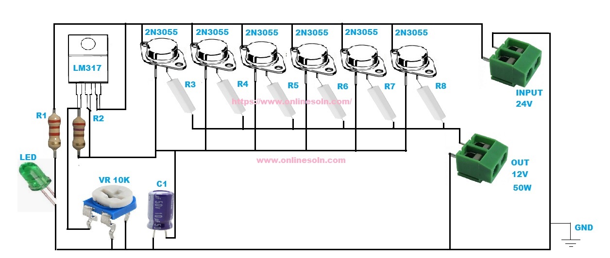
24v to 12v converter circuit
R1=2.2K
R2=270
R3-R8=0.47/10W
24v to 12v converter circuit is nothing more than an integrated adjustable voltage regulator that acts on a group of power transistors in parallel. These transistors can be said to perform heavy duty while the regulator responsible for controlling them.
Where 24 v input connector of the battery. 12V connector is the output and Gnd connector must be grounded. all the components (transistors and integrated) should be given with good heat dissipation and electrically insulated from the metal.
24v to 12v converter Adjustment
Place the pot 10 k Ω at its maximum (fully open or 10 k Ω) and connect to the dc to dc converter output a lamp 12V / 50W. At the input connect the battery in series so the voltage is reached 24V. Place the output in parallel with the lamp tester a continuous scale with the right completion (around 50V). Begin to turn the potentiometer until the brightness of lights and tester showed 12V.

I just have to introduce this hacker that I have been working with him on getting my credit score been boosted across the Equifax, TransUnion and Experian report. He made a lot of good changes on my credit report by erasing all the past eviction, bad collections and DUI off my credit report history and also increased my FICO score above 876 across my three credit bureaus report you can contact him for all kind of hacks . Email him here support@wavedrive.tech go on their website wavedrive.tech for more details,Whatsapp No:+14106350697 if you want to chat them up,One thing i can assure you would not regret this at all he is 100% legit.