555 Timer
When a 555 Timer is configured in bistable multivibrator; its output is either high or low logic signal. Here we use the simple logic that when trigger pin is grounded, output is a high logic signal and when reset pin is grounded, output is low logic signal.
The circuit for a bistable multivibrator using the 555 timer is shown below
A bistable multivibrator is one of the easiest circuits that can be built using a 555 timer. It doesn’t require a capacitor as the RC charging unit is not responsible for the generation of the output. The generation of high and low outputs is not dependent on the charging and discharging of the capacitor in the RC unit but rather it is controlled by the external trigger and reset signals.
The explanation of the bi stable mode of operation of the 555 timer is as follows. The trigger and reset pins (pins 2 and 4 respectively) are connected to the supply through two resistors R1 and R2 so that they are always high. In all the previous cases, the reset pin is not used and in order to avoid any accidental reset, it is simply connected to VCC.
Two switches are connected between these pins and ground in order to make them go low momentarily. The switch at the trigger input will act as S (SET) input for the internal flip-flop. The switch at the reset input will act as reset for the internal flip-flop.
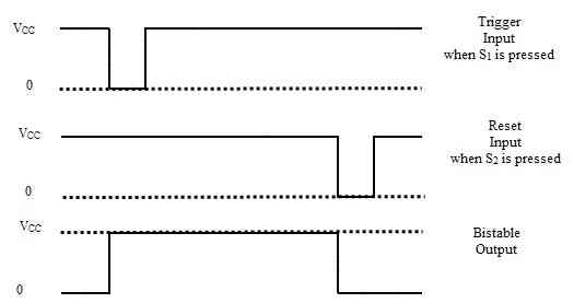
When the switch S1 is pressed, the voltage from VCC will bypass the trigger terminal and is shorted to ground through the resistor R1. Hence, the trigger pulse will momentarily go low and the output of the timer at pin 3 will become HIGH. The output stays HIGH because there is no input from the threshold pin (pin 6 is left open or better if connected to ground) and the output of the internal comparator (comparator 1) will not go high.
When the switch S2 is pressed, the voltage from VCC will bypass the reset terminal and is shorted to ground through the resistor R2. This pin is internally connected to the RESET terminal of the flip-flop. When this signal goes low for a moment, the flip-flop receives the reset signal and RESETs the flip-flop. Hence, the output will become LOW and stays there until the trigger is applied. The wave forms of the bistable mode of operation of the 555 timer are shown below.

