AUTOMATIC CONVEYOR BELT FOR INDUSTRIAL AUTOMATIONS

Most of the industry loads and goods (i.e. in warehouse, manufacturing and production facilities) are heavy to be carried by human. Using human as carrier decrease Industry efficiency and can cause fatal injury and other long-term health risks to workers
The system proposed is “Automatic Conveyor belt for Industrial Automation”. This system will be a simple and portable carrier of industrial loads in assembly line and transportation facilities. The system will be automatic in such a way that movement will only be possible when there is a load on the belt.
Block Diagram Description
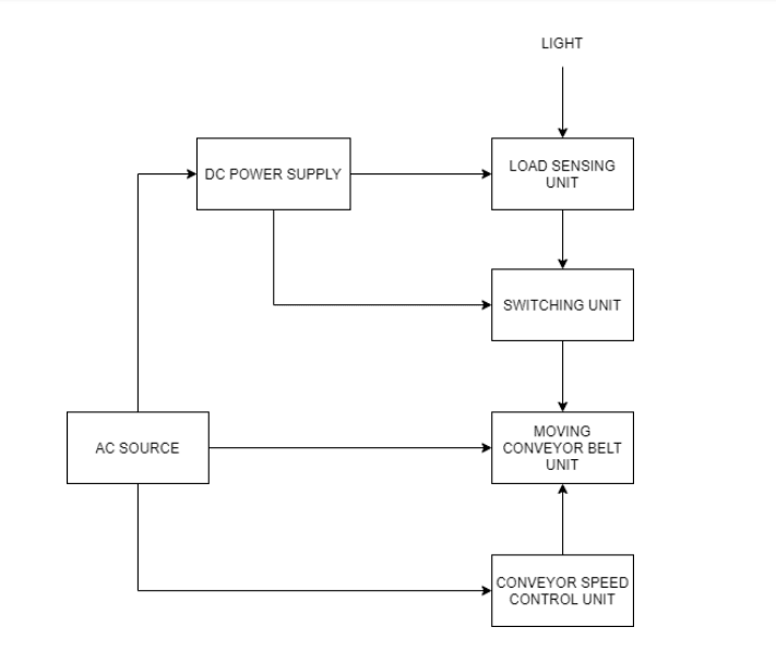
The operation of the proposed system can be explained by outlining the basic function of each individual block or component on the block diagram above as follows
Regulated Power Supply The system will be operated by both AC and DC power sources. The AC source will be used to operate the motor used to rotate the conveyor. The DC source will be a regulated i.e. producing a constant DC output for variation of input line and load.
Load Sensing Unit This unit is responsible to detect the load placed on the belt in order to initiate the movement of the conveyor belt. Load Sensing Unit works on the principle for signal interference from transmitter to receiver. There are two states of load sensing unit operation.
- No-load condition – In this state, no load will be on the conveyor meaning the conveyor will not be moving
- Load condition – On placing the load on the conveyor, the conveyor belt will start to move to transport the items from one location to another. The load sensing unit is divided into two separate units for load detection which are signal transmitter and signal receiver unit.
Signal Transmitter Unit The purpose of this unit is to generate and transmit Infrared Ray (IR) signal of a desired frequency that is going to activate or deactivate the signal receiver part
Signal Receiver and Timer Unit This part of the system will be mainly composed of IR sensor to detect the IR signal from the signal generator unit. This part will be placed on the opposite side of the conveyor belt. The blockage of the IR signal from signal transmitter unit to signal receiver unit will be interpreted as the load-condition on the conveyor and this will trigger the conveyor belt to rotate, conveying the placed object from one side of the conveyor to another.
Moving Conveyor Belt Unit This part will be mainly comprised rotating belt conveyor which will be triggered to start and stop operating by signal receiver unit. A belt conveyor consists of a minimum of two pulleys with a continuous loop material – the conveyor belt – that rotates about them. One or both pulleys are powered, moving the belt and the material on the belt forward. The powered pulley is called diver pulley while the unpowered pulley is called idler.
Motor Speed Control Unit This part can be used by the operator to regulate the speed of the rotating conveyor belt.
CIRCUIT DIAGRAM
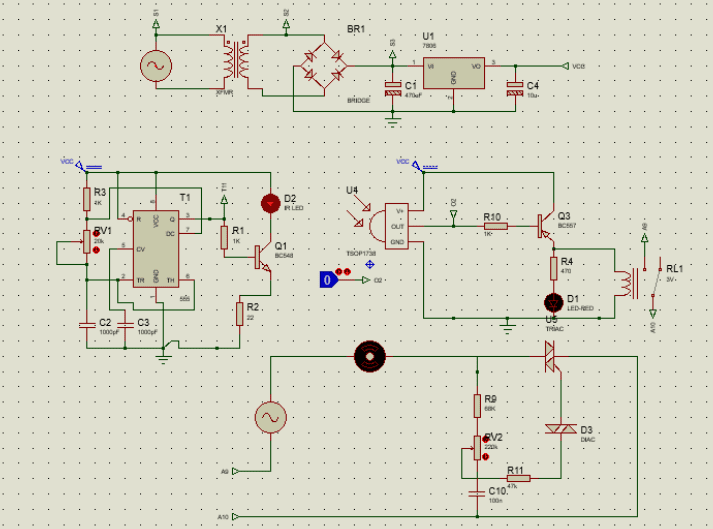
Circuit Operation
The transmitter is built around timer IC 555, which is used as an astable multivibrator to generate around 38 kHz frequency. The timer output is fed to transistor Q1, which drives the IR LED (D2). Note that IR LED must be properly oriented towards the IR sensor module of the receiver circuit. Its transmission wavelength of 900 to 1100 nm lies in the peak receptivity range of TSSP4038 receiver module. The receiver circuit comprises of the sensor module (TSSP4038). The sensor module is sensitive to IR radiation modulated at 38KHz. Its normally high output goes low when IR radiation is interrupted. When IR rays falling on the receiver are interrupted the output of the sensor goes to low state (0V) and trigger transistor Q3 to conduct enabling relay to operate the speed control 9 circuit. The motor is attached to a motor speed control, in which the motor is speed is adjusted via a variable resistor RV
Circuit Components
The circuit of automatic conveyor belt consist of the following components
- Transistor Polarity: NPN
Operating Temperature: 150C
Power: 0.625W
Maximum Vcb: 50v
Maximum Veb:6V
Maximum Ic:0.1A
BC547 - Diode Operating temperature: -55C – 150C
Peak forward voltage: 1V
Maximum RMS Voltage: 400V
Maximum DC blocking voltage: 280V
Maximum repetitive reverse voltage:
400V
1N4007 - IR Receiver Output: Active Low
Shield against electrical disturbance
Low power consumption
Immunity against ambient light
Supply Voltage: -0.3V – 6.0V
Supply Current: 5A
Output voltage: -0.3V – 6.0V
Output Current: 5A
TSSP4038 - 555 Timer Turn off time: 2Us
Max operating frequency: 500KHz
High output current
TTL compatible
NE/SA/SE5555 - Capacitor Type: Radial
Temperature: -30C to 125V
0.1uF/25V
0.01uF/50V
6.8uF/25V
100uF/25V
100nF/ 400V, - IR LED Reverse Voltage: 5V
Reverse Current: 100uA
1
14
Continuous forward current: 35uA
Operating temperature range: -40C –
85C - AC Motor
- Transformer 1:40 ratio, required output is 6VAC
- Resistor
- Relay 12V,
240 Coil resistance - Regulator (LM7806)
- Conveyor Belt Length:
Thickness:
Strength: - Driver Pulley Diameter: 10cm
- Stator Pulley Diameter: 10cm
- Transformer
- Rectifier
- Filter
- IR Transmitter
- IR Receiver
- Motor speed control unit
- Voltage regulator