ALARM SYSTEM CIRCUIT DIAGRAM
Existing system.
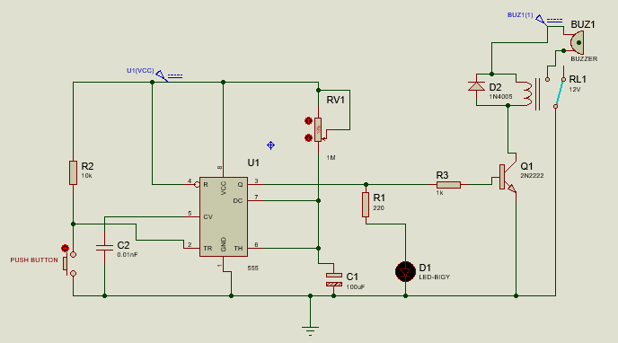
Push Button alarm system
The mode of operation for Push Button Alarm system in Figure 2.1 starts at the Push button as the sensing input signal element. When a person gently Push the Button it will generate the signal that will alert the occupant on the arrival of that person at the House’s entrance Door by turning ON the speaker placed inside the House. The Prank knocking on Door occurs due to improper way of operating it.
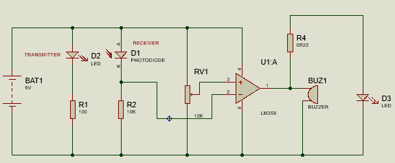
Doorbell Alarm System Using IR sensor circuit diagram.
The mode of operation for Doorbell Alarm System Using IR Sensor in Figure 2.2 is that, when someone is at the door the speaker turns whereas the IR LED light will be blocked to fall on photodiode, the Speaker will be OFF when there is no person at the entrance Door of the building the LED light will be incident on the Photodiode. Prank knocking on Door can be used and it is due to improper way of Operating of the system.
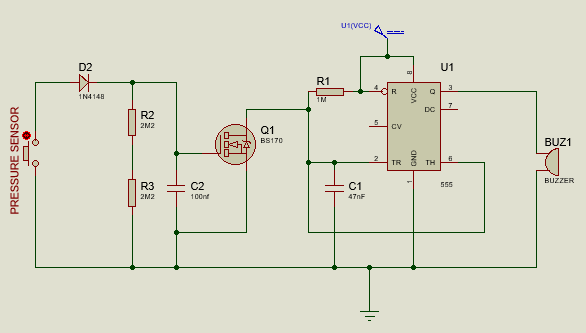
Carpet Doorbell Alarm System circuit diagram.
whenever the pressure sensor element is gently tapped by a person arrives at the Entrance Door the input signal will be generated that will turn ON the speaker to alert on the arrival of that person, whereas Mosfet (Q1) is fired by the electric pulse from the sensor and IC is enabled by the output of the (Q1) as a result the piezo sound start to beep for a short period of time set by the in circuit values of resistor (R1) and capacitor (C1).The Prank Knocking on Door can be used in this system due to improper way of operating the system.


