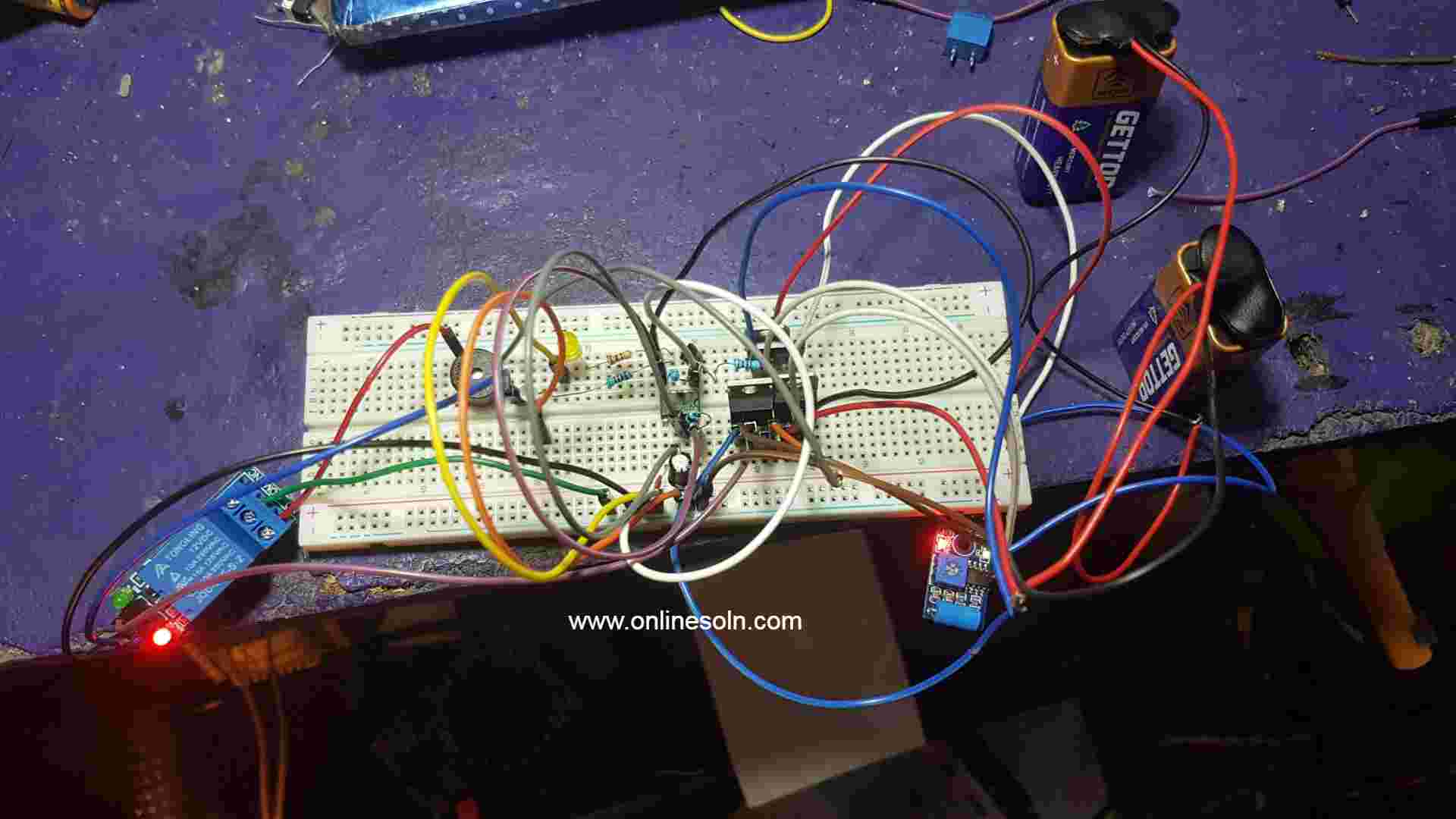
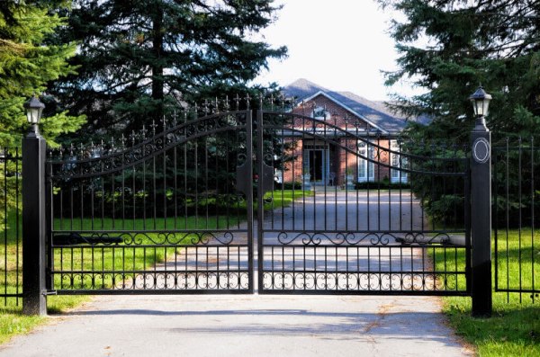
DOOR KNOCK VIBRATION ALARM SYSTEM.
Doorbell alarm system is the device installed at the entrance door serves to alert the House owner on the presence of someone at the Door. When a person arrived at the entrance of the Building it will generate the input signal that will alert the Occupant inside the Building.
Doorbell alarm system is a signaling system commonly found in houses, usually consist of a button with external device at a door of house entrance to allow a person to operate it on arrival and alerting the occupant of the house.
i. Elimination of Disturbance from Uncivilized people.
ii. Escape from the Door Bell switch Damage.
iii. It requires low Maintenance Cost.
Proposed System.
The Proposed system in Figure 2.6, will help to solve this problem, by eliminate the influence of Prank knocking on the Door. This is by replacing the function of Push button with Vibration sensor attached at the door.
The Block Diagram
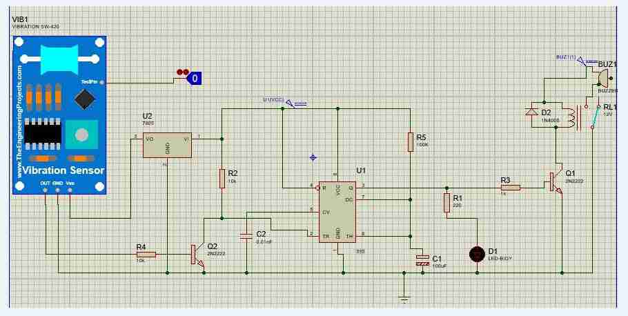
The Circuit diagram
According to the circuit above when a person arrives at the Entrance of the Building the vibration at the Vibration sensor (SW 420) located at the entrance gate of the House provides the input signal to the system and it will turn ON the speaker located inside the Building to alert the occupant on the arrival of that person, the voltage regulator (U1) helps to provide the constant input voltage to the Vibration sensor to protect against damage. The vibration sensor gives negative pulse output signal passing through transistor (Q1) which eventually act as a switch and The IC 555 timer (U1) in response to the Vibration sensor output provides the timing and delay interval to the Buzzer and LED (D1) with the operation of RC combination of resistor (RV1) and capacitor (C1).
Description of each part of a block diagram
Power Supply
This section is responsible of power provision to enable the operation of the whole system.
Sensing Element
The section consists of SW 420 vibration sensor which provides the operation of input signal detection for the system to operate. When the module is stable, the circuit is turned on and the output is High and briefly disconnected when the Vibration occurs.
Timing Circuit
This part consists of 555 timer integrated circuit provides delay and timing interval in response to the Input signal for the system to alert properly. Timing operation is controlled with the Resistor and capacitor combination connected at Threshold pin and Discharge Pin of 555 timer
Switching Circuit
This circuit provides the on and off operation of the system in response to the Input signal and time interval from the Timing circuit. The operation is controlled by the Transistor act as a switch
Alert Element
The last section gives the outcomes in form of sound in response to the present signal detected, alert when the input signal is high and does not alert when the input signal is low
In accomplish the project data were collected from different sources apart from internet Browsing and reading different books data were also collected from circuit components.
Table 4.1: Data Collected at a Case Study through Observation.
These are the measurements taken at the place where the system will be installed.
|
Detail
|
Value
|
|
Maximum Width of Door
|
240cm
|
|
Maximum length of Door
|
350cm
|
|
Material of the Door
|
Wood or Iron
|
|
Position of the system
|
At the center of the Door
|
Circuit Component.
The circuit of the Door knocking vibration alarm system consists of the following components Vibration sensor (SW420), Voltage Regulator, n-p-n Transistor, IC 555 timer, Resistors, Capacitor Variable resistor, Relay Buzzer.
Vibration Sensor (SW420).
When the module is stable, the circuit is turned on and the output is High. When the vibration occurs, the circuit will briefly disconnected and output low. The device is locally available in a cost .
Features of Vibration Sensor (SW420).
i. Non directional.
ii. High sensitivity.
iii. Respond to Vibration.
iv. Waterproof.
v. Compression resistance.
Necessary Parameters of Vibration Sensor (SW420).
i. Operating Voltage: 3.3V / 5V.
ii. Interface: Digital.
iii. Dimension: Length(40mm), Width(20mm), Height(10mm).
iv. Weight: 10g.
Vibration Sensor SW 420
Circuit diagram of Vibration Sensor SW 420
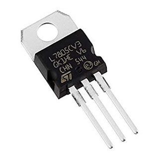
Voltage Regulator (7805 IC)
It is the component that is responsible for providing a steady DC voltage to an Electronic load. 7805 IC a member of 78XX series of fixed linear voltage regulator, the XX in 78XX indicates the output voltage it provides.7805 IC provides +5 volts regulated power supply with provisions to add heat sink. The component is locally available in a cost .
Necessary Parameter of Voltage Regulator (7805 IC)
i. Input Voltage range: 7V-35V.
ii. Current rating: 1A.
iii. Output Voltage range: Maximum Voltage=5.2V, Minimum Voltage=4.8V.
Voltage Regulator 7805 IC
Circuit Diagram of Voltage Regulator 7805 IC
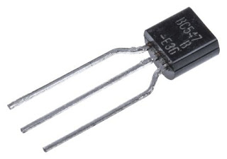
N-P-N Transistor.
When a sufficient voltage (Vin > 0.7 V) is applied between the base and emitter, collector to emitter voltage is approximately equal to 0. Therefore, the transistor acts as a short circuit. The collector current Vcc/Rc flows through the transistor. Similarly, when input voltage (Vin < 0.7 V) is applied at the input, transistor operates in cutoff region and acts as an open circuit.The component is locally available in a cost .
Necessary Parameter of N-P-N Transistor
Saturation region:
i. The input and base are connected to Vcc
ii. Base-Emitter voltage VBE> 0.7V
iii. Base-Emitter junction is forward biased
iv. Base-Collector junction forward is forward biased
v. Transistor is ON
vi. Ic=Vcc/RL
vii. VOUT=VCE=0
Cutoff region:
i. The input and Base are grounded (0v)
ii. Base-Emitter Voltage VBE< 0.7v
iii. Base-Collector junction is reverse Biased
iv. Transistor is OFF
v. No collector current flow (IC = 0)
vi. VOUT=VCE=VCC=1
n-p-n Transistor
Symbol of n-p-n Transistor
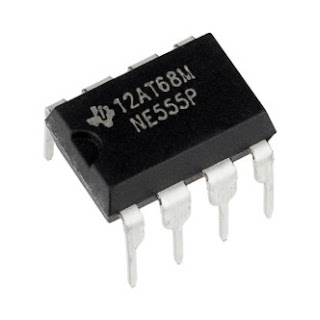
IC 555 Timer.
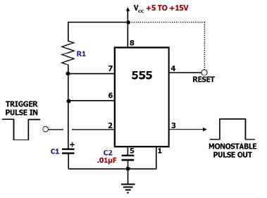
555 timer configured as monostable in a proposed circuit function as one shot, it produces one pulse of set length in response to a trigger input. An external RC network is connected between the supply voltage and ground gives the operation of time interval and delay of the 555 timer output signal. Whenever a trigger pulse is applied to the input the 555 timer will generate its single duration output pulse depending upon the values of external resistance(R) and capacitor(C) used, the output timing pulse may be adjusted from approximately 1-millisecond to as High as Hundred seconds.The component is locally available in a cost .
Features of 555 Timer.
i. Timing Interval and Delay.
Necessary Parameters.
i. Configured as monostable mode
i. Operating voltage; 5v
ii. Power dissipation; 600mW
iii. Supply current; 200mA
iv. Dimension; 4.90mm×3.91mm
v. Why using 555 timer; can be used to provide time delays, as an oscillator.
555 Timer
Monostable with 555 timer
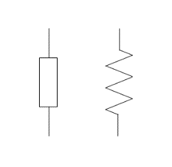
Resistor.
This is an Electronic component that reduce the flow of electric current in a circuit. There are three types of resistor these includes Carbon Composition Resistor, Carbon Film resistor and Metal film resistor.The component is locally available in a cost .
Features and Necessary Parameters of Resistor.
i. Temperature Coefficient of Resistance (TCR): wide range of TC values available from plus/minus 1 ppm/⁰C to plus/minus 6700 ppm/ ⁰C.
ii. Power rating: Standard power ratings range from 1/16th of a watt to 300 watts.
iii. Noise: depends on the material that composes it, the applied voltage, and physical dimensions of the resistor.
iv. Tolerance: Tolerances range from 20% to a fraction of one percent. Precision wire wound resistors can sport a tolerance as low as 0.005%.
v. Frequency response.
vi. Stability: the repeatability of the resistance of a resistor when measured at a reference temperature and subjected to various operating and environmental conditions.
vii. Voltage rating.
Resistors
Symbols of Resistor
Capacitor.
This is an electronic component that is used to store charge. In a proposed circuit two different types of capacitors have been employed these include Polarized capacitor and Generic non electrolytic capacitor. 100uF,0.01nF are capacitors used in a proposed circuit. The component is locally available in a cost .
Features and Necessary Parameter of Capacitor.
i. Working Voltage: the maximum continuous voltage either DC or AC that can be applied to the capacitor without failure during its working life
ii. Tolerance: the extent to which the actual capacitance is allowed to vary from its nominal value and can range anywhere from -20% to +80%.
iii. Leakage current: result of electrons physically making their way through the dielectric medium, around its edges or across its leads and which will over time fully discharging the capacitor if the supply voltage is removed.
iv. Working temperature:
v. Temperature Coefficient: maximum change in its capacitance over a specified temperature range
vi. Polarization:
Equivalent series resistance: AC impedance of the capacitor when used at high frequencies
Capacitor
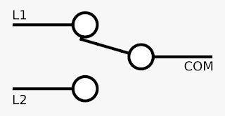
Relay.
Is an electrically operated switch. It consists of a set of input terminals for a single or multiple control signals, and a set of operating contact terminals. Single pole single throw (SPST), Single Pole Double Throw(SPDT), Double pole Double Throw (DPDT) and Double Pole single throw (DPST). In a proposed circuit have employed a SPDT relay. The component is locally available in a cost .
Features of SPDT Relay
i. High Switching Current.
ii. SPDT Relay.
iii. Normally closed relay.
Necessary Parameters of SPDT Relay
i. Frequency Range: From 7.05Ghz to 10Ghz
ii. Impedance:50 Ohms
iii. Operating Voltage:12V
iv. Actuating Current 471mA to 786mA
SPDT relay
Symbol of SPDT
Buzzer.
This is the signaling device that gives the output in form of sound. The component is locally available in a cost .
Buzzer
Symbol of Buzzer
Necessary Parameter for Installation of the System.
i. Vibration sensor should be attached at the Center of the Entrance Gate of the Building.
ii. Vibration sensor should be place at the Height of 1.6m to 1.7m (Height of an Average Human Being).
iii. Buzzer should be placed inside the Building in such a way the sound can be heard easily.
iv. The system can be Installed in both Iron and Wood gates
v. For a proper working condition of the Vibration sensor, the system should be installed on Swing Gate because it will help to eliminate from false vibration signal
Swing Gate
Tools and Equipment.
The following are tools and Equipments used according to the tactics applied.
List of Equipments used
|
S/N
|
TOOLS/EQUIPMENT
|
QUANTITY
|
|
1
|
MULTIMETER
|
1
|
|
2
|
SOLDERING IRON
|
1
|
|
3
|
SOLDERING WIRE
|
1ROLLER
|
|
4
|
BREADBOARD
|
1
|
|
5
|
VEROBOARD
|
1
|
List of components used.
|
COMPONENT NAME
|
ABBREVIATION
|
SPECIFICATIONS
|
REQUIRED AMOUNT
|
|
RESISTOR
|
R1
|
220
|
1
|
|
|
R2,R4
|
10k
|
2
|
|
|
R3
|
1k
|
1
|
|
|
RV1
|
1M
|
1
|
|
CAPACITOR
|
C1
|
100uF
|
1
|
|
|
C2
|
0.01nF
|
1
|
|
VOLTAGE REGULATOR
|
U1
|
7805
|
1
|
|
TRANSISTOR
|
Q1,Q2
|
n-p-n 2N2222
|
2
|
|
RELAY SWITCH
|
RL1
|
12V
|
1
|
|
BUZZER
|
BUZ1
|
|
1
|
|
555 TIMER
|
555
|
|
1
|
|
VIBRATION SENSOR
|
VB1
|
SW-420
|
1
|
|
LED
|
D1
|
|
1
|
