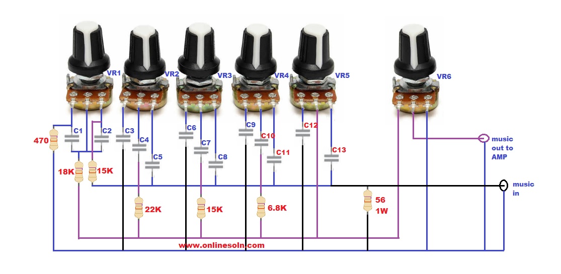
5 Band Passive Equalizer Circuit
A very neat and reasonably efficient 5 band graphic equalizer circuit using only passive components can e built as shown in the following diagram:
Resistor; (ohm)
VR1,VR2,VR3,VR4,VR5; 50K
VR6; 10K
Capacitor; ( F)
C1; 220n
C2,C4; 22n
C3,C9; 47n
C5.C10,C11; 4.7n
C6; 100n
C7,C8,C12; 10n
C12; 1n
As can be seen in the Circuit above, the 5 band equalizer has five potentiometers for controlling the tone of the input music signal, while the sixth potentiometer is positioned for controlling the volume of the sound output.
Basically, the shown stages are simple RC filters, which narrow or broaden the frequency passage of the input signal, so that only a certain band of frequency is allowed to pass, depending on the adjustment of the relevant pots.
The equalized frequency bands are 60Hz, 240Hz, 1KHz, 4KHz and 16KHz, from left towards right. Lastly followed by the volume control pot control.
Since the design does not use active components this equalizer is able to operate without any supply input. Please note that if this 5 band equalizer is implemented for a stereo or multichannel system, it may become necessary to set up an equalizer in the identical manner for each of the channels.

can i remove the volume pot?
Yes, you can, what happen only frequency bands remains without volume control
https://www.onlinesoln.com/2020/05/equalizer-circuit-diagram-5-band.html
is it possible to increase the number of frqeuncies by adding more pots and elements to the circuit?
yes! you can do that.
I know a professional hacker cyberspysolution@gmail. com who has worked for me once this month. He offers legit services such as clearing of bad records online without being traced back to you, He clone phones, hack Facebook account, instagram, WhatsApp, emails, Twitter, bank accounts, Skype, FIXES CREDIT REPORTs, track calls. He also help retrieve accounts that have been taking by hackers. His charges are affordable, reliable and 100% safe. Contact him via address below…
Email…cyberspysolution@gmail. com
Whatsapp:.+1(832) 413-3896
I feel there is a mistake. C5 should be 47nF not 4.7nF It is the Cap for 240Hz band. Has anyone made this ?. If C5 is 4.7nF it is blocking most 240Hz. i.e it's reactance is 141k ohms. If C5 is 47 nF, it's reactance is 14k ohms at 240 Hz, and that correlates with the other caps at the other bands.. eg: 1kHz 15.9k ohms, 4kHz 8k ohms, 16kHz 10k ohms
Can you please show the calculations for the frequency bands?
C13 is not specified. Should be 1nF
C10 c11 c12 c13 difference voltage pf?