Stereo plus bridge drive
Description
The STA540 is a 4-channel, class AB audio amplifier designed for high quality sound applications. The amplifiers have single-ended outputs with integrated short-circuit protection, thermal protection and diagnostic functions.
1; Minimum external components count:
- – no bootstrap capacitors
- – no Boucherot cells
- – internally fixed gain 20 dB
2; Standby function (CMOS compatible).
3; No audible pop during standby operations.
4; Diagnostic facilities:
3; No audible pop during standby operations.
4; Diagnostic facilities:
- – clip detector
- – output to GND short-circuit detector
- – output to VS short-circuit detector
- – soft short-circuit check at turn-on
- – thermal shutdown warning Protection
5; Output AC/DC short circuit.
6; Soft short-circuit check at turn-on.
7; Thermal cutoff/limiter to prevent chip from overheating.
8; High inductive loads.
9; ESD.
6; Soft short-circuit check at turn-on.
7; Thermal cutoff/limiter to prevent chip from overheating.
8; High inductive loads.
9; ESD.
Stereo plus bridge drive
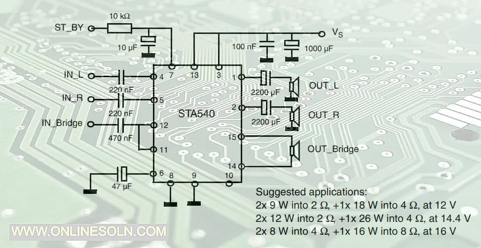
VCC = 20VDC
Capacitor
- 1000uF/25V
- 100nF = 104 Polyester capacitors
- 2200uF/16V
- 47uF/25V
- 0.47uF =474 Polyester capacitors
- 0.22uF =224 Polyester capacitors
- 10uF/50V
Resistor
- 10k/(1/2W)
The best audio performance is obtained with the configuration where each speaker has its own DC blocking capacitor
Block diagram

Pin connection (top view)
")