Audio Processor IC
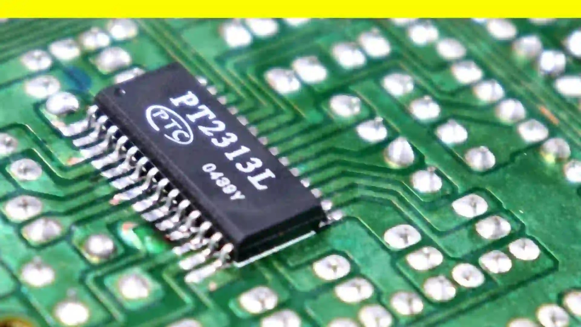
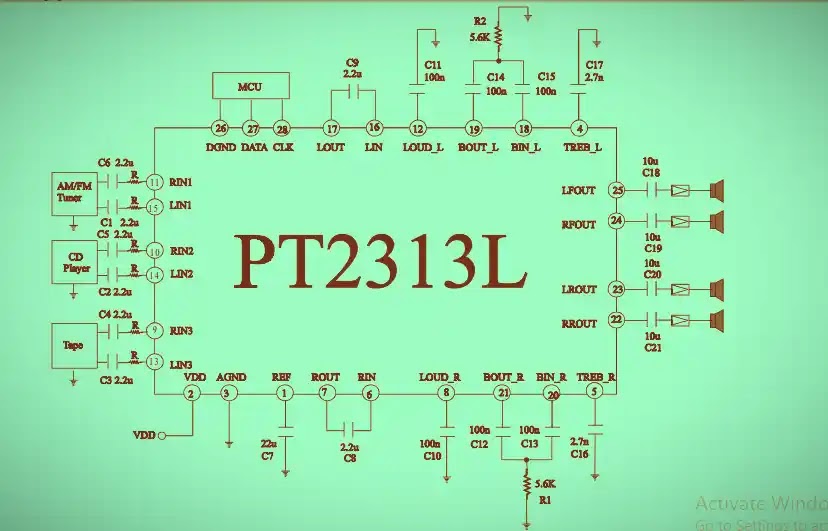
PT2313L is a four-channel digital control audio processor utilizing CMOS Technology. Volume, Bass, Treble and Balance, Front/Rear Fader Processor are incorporated into a single chip. Loudness Function and Selectable Input Gain are also provided to build a highly effective electronic audio processor having the highest performance and reliability with the least external components. All functions are programmable using the I2 C Bus.
The pin assignments and application circuit are optimized for easy PCB layout and cost saving advantage for audio application. Housed in a 28-pin DIP/SO Package, PT2313L is pin-to-pin compatible with TDA7313 and is very similar in performance with the later.
Features
- CMOS Technology
- Least External Components
- Treble and Bass Control
- Loudness Function
- 3 Stereo Inputs with Selectable Input Gain
- Input/Output for External Noise Reduction System/Equalizer
- 4 Independent Speaker Controls for Fader and Balance
- Independent Mute Function ! Volume Control in 1.25 dB/step
- Low Distortion ! Low Noise and DC Stepping
- Controlled by I2 C Bus Micro-Processor Interface
- Pin-to-pin Compatible with TDA7313
Note:
- The Resistor ( R ) Range = 2.0K Ohms to 3.6 K Ohms.
- Resistor ( R ) Recommended Value = 2.4 K Ohms
Applications
- Car Stereo (Audio)
- Hi-Fi Audio System


It is ready made audio programmable ic