LOCATING THE FAULT STAGE FROM FAULT SYMPTOMS

Defects can occur in the receiver due to failure of some components such as an IC, transistor, resistance, condenser or picture tube etc due to loose or broken wires, loose or dry joints or some defect in PCB. The main job in troubleshooting is to locate the faulty components in the shortest time.
TV receiver troubleshooting can be divided into the following steps.
i. Locate the defective stage/section from the fault symptom.
ii. If the defect result in dead receiver that there is no sound and no light on the screen, it is likely to be in the main power supply or auxiliary power supply. Check the voltage on these areas to ascertain defective stage.
iii. If the defect appears to be in the signal chain that is, normal sound or normal black and white picture is not received the defect may be in the tuner, video IF, video per amp or in the sound section. In this case the faulty stage should be located from fault symptoms followed by signal substitution testing.
iv. If the defect appears to be in the colour section i.e. normal black and white picture is received but there is no colour or else the colours are not normal try to ascertain the fault stage from the fault symptoms.
v. Once the fault has been indicated and if necessary by using the signal substitution, check the voltages at various points in the suspected stage.
vi. Test or replace the suspected component.
vii. Check the servicing adjustments/alignment and if necessary re-adjust these as required.
For quickly locating the defects, these steps should be followed systematically.
Principles of locating the defective stage from fault symptoms.
The fault stage or section can be located by analyzing the fault symptoms. The analysis is based on the assumption that there is only one defect (which is usually the case) in the receiver which is causing the in operation or faulty operation of the TV receiver.
Consider the case of a receiver in which the raster is normal but there is no picture and no sound. The following points arise in this case-
i. The raster is there hence both sweep sections are working normally, the auxiliary supply is normal and the high voltage supplies are more or less normal.
ii. Stages common to both picture and sound may be defective. These stages are the tuner and the video IF section.
Consider the case there is sound but the raster and picture are normal. The following conclusions may drive this case-
i. Sound section is defective ie either sound IF or sound output section.
Sound and black and white picture are normal but there is no colour.
i. Chroma section is likely to be defective.
TV RECEIVER DEFECTS AND LIKELY DEFECTIVE STAGES
|
Defect
|
Likely defective stage
|
|
No light on screen and no sound
|
i. Main power supply
ii. Auxiliary power supply
|
|
No raster and no light, sound normal
|
i. EHT rectifier or connected circuit
ii. Picture tube stage (biasing circuit, heater circuit, open heater, colour signal output stages)
|
|
No picture and no sound-raster normal with some snow
|
i. Feeder- open or short
ii. Tuner
|
|
No picture and no sound, raster normal with no snow
|
i. Video IF section
|
|
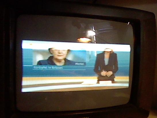
No picture, raster and sound are normal
|
i. Video IF section
ii. Video amplifier
|
|
Only bright horizontal line is traced on the screen-failure of vertical sweep
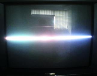 |
i. Vertical sweep section
ii. Vertical deflection coil (open)
iii. Leads from vertical output to the vertical deflection coil (open or dry joints)
|
|
Reduced picture height
 |
i. Height control incorrectly set or defective
ii. Vertical sweep section
|
|
Picture rolls upwards or downwards (vertical instability)
 |
i. Vertical oscillator
ii. V hold control defective or incorrectly set
iii. Sync separator
|
|
Slanting line or pattern is displayed on screen (H instability)
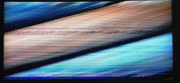 |
i. Sync separator
ii. AGC circuit
|
|
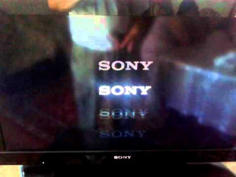
Insufficient bright-ness
|
i. Video amplifier
ii. Chroma section
iii. Brightness control defective
iv. Picture tube circuit (proper voltage is not reaching some of the pins)
|
|
Insufficient contrast
|
i. Aerial or feeder (the snow will be excessive)
ii. Video IF section
iii. Video amplifier
iv. Wrong setting of AGC control
|
|
Picture height and width are less (the picture will be dull at otherwise normal settings of brightness control)
|
i. Mains power supply (low voltage), since the output of the power supply is stabilized this effect will occur only when
– Rectifier defect
– Regulator defect
|
|
No sound, low sound or distorted sound- raster and picture are normal
|
i. Sound IF subsection
ii. Sound output
|
|
No colour, black and white picture normal
|
i. Aerial- some section broken aerial off the correct direction
ii. Feeder- one limb open
iii. Tuner
iv. Video IF section
v. Chroma section
|
|
Insufficient colour
|
i. Chroma section
ii. Colour control or connected circuit
|
|
Specific tinted colour
|
i. R,G and B output stages
ii. Chroma section
|
|
Very dully picture
|
i. Video amplifier
|
|
Colour impurity
|
i. Setting of colour purity magnets
ii. Magnetised picture tube
|