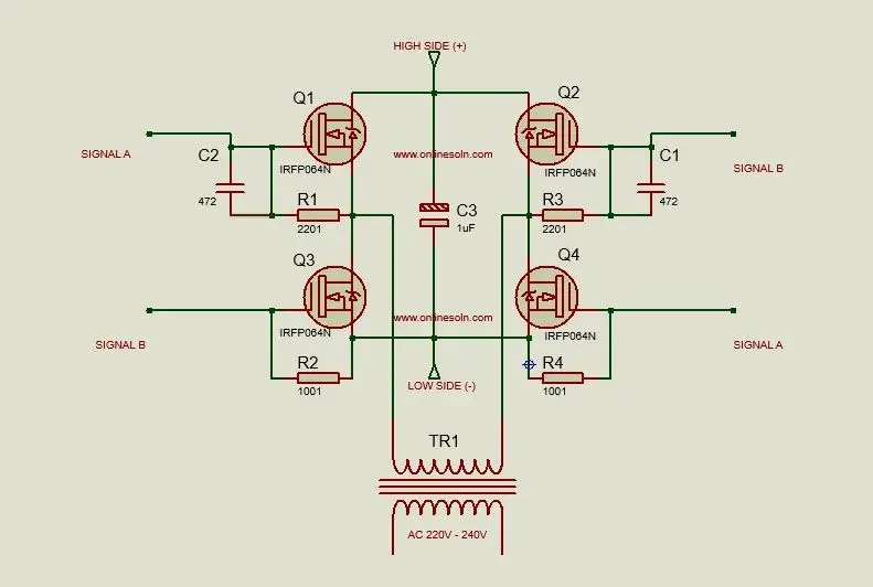
Full bridge power inverter connections.
The switching frequency used in this project is 50Hz. It is desired to control the inverter with proper switching signals. The turn on and turn off time of the switches is determined by this PWM control signal generated by IC controller. Before this control signal is being generated, proper calculation is done to determine the suitable switching pulses conditions (frequency) for the switches.
Below shows the approach in which the controller outputs are connected with the inverter MOSFET switches as used in this work. The turn ON and OFF for Q1 and Q4 are controlled by PWM Signal A . While the turn ON and OFF for Q2 and Q3 are controlled by PWM Signal B. Both PWM Signal A and PWM Signal B used the same control signal generated by the IC. With PWM Signal A signal leading PWM Signal B by half cycle or 180 degree of the switching signal.
High side voltage ( 12V )
The Controller Circuit using PWM IC This serves as the controller. It produces PWM pulses and these pulses are provided to the MOSFET switches such that the MOSFET gates can be triggered ON and OFF. This is responsible for generating oscillating signals that controls the ON and OFF action of the MOSFET switches
If you have any comments or ideas about this post please write me a comment below
