Problem Statement
The nation faces a constant problem to supply power to rural areas due to inaccessibility of rural areas. It is extremely costly to provide electricity to rural areas through conventional means. Currently, in rural areas, most of the schools, health centers, administration posts, small commercial centers and other communities use solar power or fuel generators for each home. Instead of providing isolated solar systems for each home or fuel generator. The extension of the grid through the utilization of SWER in distribution network for electrification of the whole community in rural villages would be more economical and reliable.
Main Objective
To design and implement of single wire earth return electrification scheme (SWER) at Mtowisa.
Specific Objective
- To estimate the load profile of a typical settled rural area
- To design a radial network to distribute power to the selected area from the grid extension
- To design heating system of electrode due to continuous current flowing.
Significance of The Project
- The system is cheap in terms of material used and hence make it affordable even for the people with low income
- Also, the system requires little now and then maintenance and hence has minimum maintenance cost
- The system minimizes electrical fault comparing with existing power transmission system
Methadology
- Here are some steps to follow for methodology
- Literature review
- Data collection
- Data analysis
- Designing the circuit
- To simulate the circuit diagram
- To build and testing the prototype Report
- Report writing
Disadvantages of Existing System
The system is most expensive for power distribution compared to single wire earth return (SWER).
The system has more faults since both conductors are run overhead.
Indicators (LEDs).
Recall from data sheet provided By, ohms law calculation
Current passing through LED,
LEDS, Red 2V=15mA
Green 2.1V=20mA
Blue3.2V= 25mA
White 3.2= 25mA
Power Protection and current Limiting
I. Resistor
Resistor = (power supply source – LED volts)/Desired LED current
Recall the formula calculation for Resistor
12-2.1 =9.9V
I= 20/1000A
R=520 ohm.
Use resistor (500ohms up to 1K for led current limiting
Fuse.
Since the total power of our circuit is 36W Now we need to find the required size of fuse to handle the load from dc supply of 12v dc.
From equation
P = V I, then 36w =12 *I
I = 3A ( Fuse Rating)
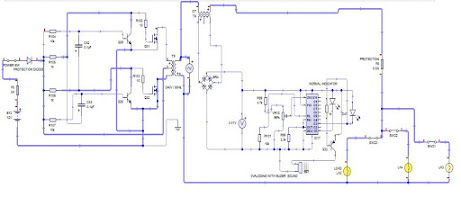
CIRCUIT DESIGN